2018/01/31

WinOLS software corrects checksums (photos)

So here is a little tutorial – how to make checksums for ecu files with Winols tuning software, that should help all of you who don’t know how to do this get started using Winols.

Winols 2.24 software download:
Checksums are very important, get them wrong and car won‘t start or even worse
1. If you haven’t installed Winols 2.24 first, then do so, it can be found here on CT using the search button, this is not the search box
2. Open Winols, and after you will see the empty working box, picture 1A. Now drag and drop your ecu file onto this box as in picture 1B. Now in picture 1, you can see there are 3 checksums that need correcting, Winols will do this for you.
3. Follow the instructions in following pictures and this should get you started making checksum for your own files.

Run Winols
checksums-with-winols-1
Drag petio 3,.0 asn_lambda_off_nochecks.bin into Winols
checksums-with-winols-2
You will see the pop-up: 3 checksum(s) not correct
checksums-with-winols-3
Correct the original data file
checksums-with-winols-4
checksums-with-winols-5
checksums-with-winols-6
Map search in progress
All CS ok -Checksum block 5: okay
checksums-with-winols-7
Project->Ex-&Import->Export file…
checksums-with-winols-8
Enter info
checksums-with-winols-9
Select Binary file
checksums-with-winols-10
Save as petio 3,.0 asn_lambda_off_nochecks_csok.bin
checksums-with-winols-11
All CS ok -Checksum block 5: okay
checksums-with-winols-12
In summary, how to checksum correcting by Winols chip tuning software:
  1. First, drag and drop the original untouched file into Winols in the same way as in the pictures. When it has finished loading the original file …then
    2. you can now drag and drop your modified file ontop of the original file you already loaded into Winols.
    3. Now you can follow the checksum procedure steps exactly as described in the pictures, correcting modfile checksums.
Attachment:Included are two ecu files, Audi A6 3.0 lambda off ME7.1.1, one with “nochecks” (no checksum) and the other with “csok” (checksum ok).
petio 3,.0 asn_lambda_off_nochecks_csok.rar
petio 3,.0 asn_lambda_off_nochecks.rar

FAQ:
Q: I found a stage1 tuning file and while I was inserting it into Winols it says me: “This software version cannot be processed, since it is already modified” Could somebody please help me what does it mean?
A: Open the file in a simple hex editor, click search txt string NOREAD
when you find the words “noread” write over them with FFFFFF, save changes and try again with Winols

Q: If I read and write files with Kess V2 or KTag clone did they make checksum correction or must be done with Winols?
A: With those tools checksum will be done in writing

2018/01/24

Kia Magentis II 2006 PCM Reset with BDM100

DIY guide: How to reset the PCM unit of the Kia Magentis II MG 2.0L MT 2006Y.
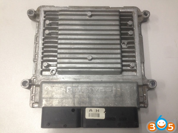
A remarkable unit SIM2K-140 , which, for example, uses the PCMFlash to read the complete dump of flash memory AM29BDD160GD , from the address 0xh to the address 1FFFFFxh , and only calibrations are written.
Actually, the story of the sad (relatively) case of replacing the calibrations in the above immo:
Kia-Magentis-II-pcm-reset-bdm100-1
MGD6K0CS2B
5WY5254C
39111-25220
DBH
Siemens VDO:
Kia-Magentis-II-pcm-reset-bdm100-2
As they told me:
The car was replaced by ICE and sort of like the calibration did not correspond to reality, accordingly bad traction, unnecessary errors, etc. Colleagues decided to fill in alternative calibrations, and they did it, but in the future the engine of the car did not start, because activated immobilizer, which in this car is missing from the factory (there is no Immo unit, antenna on the ignition lock, a chip in the key, wiring …)
This computer consists of 4 parts:
1. Bootloader – 0x0000 – 0x1FFFF (131,072 bytes)
2. Calibration – 0x40000-0x5FFFF (131,072 bytes)
3. Firmware:
___ 1st part – 0x20000-0x3FFFF (131,072 bytes)
___ 2- I part – 0x80000-0x17FFFF (1,048,576 bytes)
4. Ego Industry – 0x180000-0x19FFFF (131,072 bytes)
Accordingly, after filling the wrong calibration, the content of Eeprom was changed (according to the new calibrations the processor decided that it was Immo and registered it), which the flashers did not rewrite via the diagnostic connector .
Therefore, for the resurrection of the unit without the Immo it is necessary to dismantle it from the car, take apart, connect to the BDM programmer, read flash memory, change it, program, assemble, install on the car, start the engine and wish a happy journey.
Unlock the unit:
Kia-Magentis-II-pcm-reset-bdm100-3
The main processor Motorolla MPC561MZP56 :
Kia-Magentis-II-pcm-reset-bdm100-4
Next on the board is the desired flash memory:
Kia-Magentis-II-pcm-reset-bdm100-5
Well, a little higher and to the left of the BDM- pad:
Kia-Magentis-II-pcm-reset-bdm100-6
Connect:
Kia-Magentis-II-pcm-reset-bdm100-7
We will use BDM100 ecu programmer (MPC BDM Programmer):
Kia-Magentis-II-pcm-reset-bdm100-8
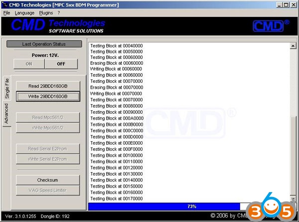
We supply power to the unit from the laboratory PC, and also power the program, run the software and press the ON button:
Kia-Magentis-II-pcm-reset-bdm100-9
Now we will read. If you use the Single file tab, the firmware is considered to be in the format of the program, which does not suit us, but we still believe. Click Read Ecu . It was considered approximately for a minute:
Kia-Magentis-II-pcm-reset-bdm100-10
Now go to the Advanced tab . Just here is what we need, specifically flash:
Kia-Magentis-II-pcm-reset-bdm100-11
Press Read, o5 is still counted for a minute:
Kia-Magentis-II-pcm-reset-bdm100-12
The single file does not interest us, its size is 425kb. A purely read 2048 kb flash is what you need. Now let’s compare the file that the colleagues initially counted from this ecu, and the one that I now subtracted, for example via WinHex . It turns out 81533 differences. Now open HexCmp2 and already clearly see the differences:
Kia-Magentis-II-pcm-reset-bdm100-13
Etc.:
Kia-Magentis-II-pcm-reset-bdm100-14
All clear. Now we will record the original file, originally read by colleagues. To do this, on the Advanced tab, click the corresponding record button and select the correct file. Then, the BDM-100 program will ask about our intentions, agree:
Kia-Magentis-II-pcm-reset-bdm100-15
In the process of writing:
Kia-Magentis-II-pcm-reset-bdm100-16
Done successfully for 2 minutes:
Kia-Magentis-II-pcm-reset-bdm100-17
Most of the way is passed, now we turn off, we unsolder the wires, we go to the place of the car ridden by colleagues:
Kia-Magentis-II-pcm-reset-bdm100-18
Connect a single connector, tk. MT. In the case of AT, there would be two connectors:
Kia-Magentis-II-pcm-reset-bdm100-19
Let’s see what’s happened. The key to the start and ICE here also started, which I even did not doubt:
Kia-Magentis-II-pcm-reset-bdm100-20
Colleagues and the car owner of course, are happy.  Because the costs of reset PCM unit are minimized.

Disclaimer:
We would like to express my gratitude to P1on3R91 from Russia for the tutorial provided. You are at your risk.

2018/01/23

2017.12 BMW ISTA+ download & install for diagnostic & programming

BMW ISTA+ download:
Free version: Go to BMW forums and download ista+ for free
BMW forums such as bimmerfest, bimmerpost,bimmerforums, bimmerboard etc   etc.

Here list a link for you to have a try:
BMW_ISPI_ISTA-P_DAT_3.63.0.400.istap
BMW_ISPI_ISTA-P_SYS_3.63.0.400.exe

Tested version: Use ISTA-D 4.08.12 ISTA-P 3.63.0.400 with relief
2017-12-icom-ista-1
2017-12-icom-ista-2
2017-12-icom-ista-3
What is ISTA and what is ISTA+:

ISTA is a workshop system that contains BMW AG Data and Information. ISTA stands for Integrated Service Technical Application. Way back when, during the initial development of this tool, BMW used DIS (Diagnostics Information System), and as the programs evolved and due to the nature of the file naming conventions utilized by BMW, the workshop system became known as Rheingold in the enthusiast world. Rheingold in actuality is the folder that contains the main application and data. Rheingold became ISTA-D (D stands for Diagnostics) and BMW’s programming application (not discussed in this document) used the same nomenclature, ISTA except with a P (for programming) or ISTA-P. This document only discusses ISTA+.

Eventually, based on the direction that the company is taking, ISTA-D and ISTA-P for F-/I-/G-/Mini/RR series cars will be rolled up into ISTA+ for diagnostics AND programming.

That is, ISTA-P will contain all chassis data until around August 2017, then BMW plans to phase out all BN2020 vehicle data in ISTA-P. So, ISTA-P will be used for Programming on E-series only and ISTA+ will be everything else.

Programming (or also called Service Data) in ISTA+ is required for programming F-/I-/G-/Mini/RR cars. BMW now provides these files as deltas to original programming (SDP) data.

ISTA+ can be used to diagnose ALL cars BUT program only F-/I-/G-/Mini/RR series cars and beyond. E Series Programming is not supported in ISTA+.

BMW officially breaks up the new ISTA+ application capability into two parts – Diagnostics and Programming. Following is a short breakup of each feature within ISTA+:
DIAGNOSTICS:
  • Vehicle identification for specific vehicle management
  • Information research for repair and maintenance
  • Guided troubleshooting
  • Software repair

PROGRAMMING:
  • Software Update
  • Control Unit Replacements
  • Retrofits / conversions


System requirement:

  • Minimum system configuration is now hard coded into the program, although the standalone versions have this check removed.
  • 2.2Ghz CPU – 2 core minimum, core i5 or i7 recommended
  • 4GB RAM, 8GB recommended
  • Minimum 20+GB HDD free space for ISTA+ Diagnostics with ONE language, and minimum 100GB for Programming Data.
  • This version has hardware check removed, however, future versions MAY not have this feature. A faster system is required.
  • This version discusses included English Databases only. If more required, add to SQLiteDBs folder, which will need more space.


ISTA+ Installation instruction:

VARY WITH SOURCE

NOTE: While there are multiple sources to procure ISTA+ and “install” on a laptop, the following instructions apply only to ISTA+ obtained on this site, and specifically asked for and received through the Rheingold/ISTA-D request thread. Each source has its own installation method and those are not discussed here. Versions in pictures used as examples only. Actual version may vary.

Step 1:
Download and run unblock.reg BEFORE downloading anything else. Then REBOOT the computer, this is a critical step.
install-bmw-ista-1
Step 2:
Install everything in Prerequisites folder, only if you don’t have a previous Rheingold installation. For 64-bit Windows, install both vcredist x32 & x64 from Microsoft, if not already installed.
install-bmw-ista-2
Step 3:
Install the following – you can get both from Microsoft.
  • Visual C++ Redistributable Packages for Visual Studio 2013
  • .NET Framework 4.6

Step 4:
Download Rheingold.7z using MegaSync or JDownloader. Once downloaded, check whether “Rheingold.7z” is blocked. If it is, unblock it. Right click on the file, go to Properties and if files are blocked, then you will see the unblock button as in the picture below:
install-bmw-ista-3
Step 5:
Extract Rheingold.7z using 7zip ONLY. You may have to give admin privileges for extracting. Location doesn’t matter, but preferred location is C:\. If extracting to this location, you will need admin privileges for 7zip before extracting the file. To avoid future issues with admin rights etc. you can also extract this file to the root of a secondary drive, for e.g. D:\
Step 6:
Assuming you extracted the file to the location suggested above, create desktop shortcut from “C:\Rheingold\TesterGUI\bin\Release\ISTAGUI.exe”. If not, create the shortcut from the location you extracted the files to.
install-bmw-ista-4
Step 7:
Run the following registry fixes, depending from your OS:
  • From the Mega site, download and run the following two registry files: o Ista-prog-x64.reg
o Ista-prog-x86.reg

  • Also run the following registry fixes from the C:\Rheingold folder (scroll all the way to the bottom to see these files):
install-bmw-ista-5
Step 8:
Run ISTAGUI shortcut from your desktop as administrator.
Step 9:
When prompted for license, copy the license key from the “rheingold-license.txt” located in “C: \Rheingold”
install-bmw-ista-6
Step 10:
If/When prompted for dealer ID, enter “1” and ignore following warnings. ISTA+ will close.
Step 11:
Run again ISTAGUI shortcut from your desktop as administrator and verify the databases in Settings > Version tab in ISTA/D If you encounter start/running issues, delete the “Rheingold” folder from “C:\”, run “RCleanerV4.4.exe” as administrator and start again from step 5.

NOTE: If you have no good source of ISTA+ download or think it hard to install ISTA+ yourself, go to have the plug-and-play, ISTA+ HDD. Just insert it into your laptop and use with relief.

2018/01/22

How to update Ktag fw 7.020 by yourself

Updating Ktag firmware to 7.020 version doesn’t block processor.
For correct operation device it is necessary to change CID SDcard on 035344535330344780399b1368010300
This procedure is supported by not each SDcard.
Programs for change of CID and the description of process easy to find in the Internet.
I used mmc32 and evoplus_cid from github. This programs for linux. I haven’t found soft working in Windows
It is difficult to find SDcard which supports change CID.
SDcards with built-in chipset of production Samsung meet such requirements.
…or buy on Alibaba, using search “CUSTOM CID”.
ktag-firmware-7020-1
CID SDcard: 035344535330344780399b1368010300
KTAG_7.020_SDcard_img:

Ktag fw 7.020 update FAQs:
Q: for upgrade ktag with 6.070 required change nxp whit crp3 status?:
A: if you use Jlink to you necessary level not above CRP1
if you use usb-com to you necessary level not above CRP2

Q: tool trick is test unlock whit airflow?
A: Yes, but sometimes it’s easier to replace LPC with new device.


Q: trick airflow whit my kess not work…send me instruction for test on ktag and i’m test trick on ktag…thanks. And i have a question…problem is my ftdi interface?
A: I think most simply to change NXP processor.
…temperature destroys the processor
It is very doubtful method

Q: After you change cid copy image with sd
A: cloning of SDcard is a big problem now
I will do SDcard for CID

Q: what linux system did you use?
A: linux version will not matter
Q: what program do the card image sd ??
A: I used mmc32 and evoplus_cid from github. This programs for linux.

Q: i have samsung 64gb change the cid an uplad the bin but all i have is this on the picture. any ideas?
A: use up to 8gB card. And check all Made in Korea for rewritable CID

Q: what was the hardware problem ???
A: not all china clones are the same, mine is missing a few components
with ktag 6.070 not have problems
there is free rework guide on the net
so i add them and all ok

Q: Write the instruction how to rewrite the CID????

Q: Can you share usb-com connections?
A: Here you go
ktag-firmware-7020-2
NOTE: Good experienced technique is required. YOU ARE TRYING ALL ON YOUR OWN RISK. If you want a Ktag firmware 7.020 with relief and use it with security, go for a tested and working one – RED Ktag 7.020 is cost-effective. Look here: http://www.obdii365.com/wholesale/ktag-v7020-red-pcb-online-version.html
ktag-7020-red-1
ktag-7020-red-2
ktag-7020-red-3
Confirmed! Working no issues!
ktag-7020-ksuite

2018/01/21

PTT 2.X.X 'older electrical system' Problem & Solution

Problem:

Does anybody can provide a manual how to use Premium Tech Tool?
I’ve got a 2011 VN at the shop yesterday that is connecting to PTT 2.5.87 and PTT 2.4.87 as older electrical system. I run this tool (with PTT closed), enter the chassis ID, select VERSION2 and the tool showed me “Done” after some time. But once i’ve connected to the truck it still being showed as older system. I’ve tried to enter chassis ID as N****** and N ****** but with no luck. Both PTT seems working good as it was installed by trusted forum member and i have no problems with other trucks.

Solution:

Step 1, Open Volvo Tech Tool, system detected OLD ELECTRICAL SYSTEM, click finish job.
– FIRST clean/remove HISTORY on LATEST SELECTION . DONT CLOSE Tech Tool!.
Step 2, Run OLD2V2 TOOL
-put chassis ID : full chassis number like this, example :YVAM390985Y036312
-select version 2 or version 3 (depend on your truck)
-hit button SET, Tech Tool will close automatic!.
-waiting until appear DONE. press it.
Step 3, Open Tech Tool back, reconnect, still detect OLD ELECTRICAL SYSTEM, don’t panic
-DONT CLICK ANY SELECTION, just view and click FINISH JOB. Don’t close Tech Tool.
-PULL OUT THE DIAGNOSTIC CABLE FROM THE TRUCK’S SOCKET AT BELOW DRIVER SIDE, (NOT USB CABLE AT LAPTOP !!) and THEN RECONNECT IT BACK.
Step 4, Wait, Tech Tool automatically will detect/retrieve NEW CONNECTION and we can change to VERSION 2 or 3 on popup MANDATORY selection box,
DONE!


About Tech Tool
Tech Tool is a tool that supports the repair and diagnostic process, developed in order to make the work in the workshops easier and more efficient. Tech Tool can be used online or offline (i.e. connected to central systems or not) in the workshop, out on the field, at the roadside or during test drives. Tech Tool is an application for diagnostic with possibility to use plug-ins to cover the whole repair process. With Tech Tool you can diagnose, test, calibrate and program a product. A product could be a vehicle, engine or a machine. Tech Tool also provide functions for updating the tool, and communication with the product and other external applications such as links to external websites or plug-ins. The set of plug-ins, user authorisations, and available languages is adjustable to provide every user with what they need.

Tech Tool menu
These menu options are available in the Tech Tool menu. Menu option Description Connect to Central Systems or Work Offline Depending on if you are working online or offline you are able to connect to or disconnect from central systems. Update Product Information Update the product information data. Administrate Software… Order different types of software. Electrical system dependent. Administrate Software New… Order different types of software. Electrical system dependent. Settings Change settings for product and network communication. See Configure Tech Tool for details. User Preferences Change language and unit settings. See User preferences for details. Print Label… Print engine labels for available chassis IDs. Print Print the displayed information. Log off Log off the current user. Exit Exit the application.

View product history
In Product History you will find the session logs. You can view the current session log or recent session logs for identified products. You can also search for session logs by date. In the logs you will find work that previously has been done on the selected product. It could be previously detected DTCs, product information and operations that have been performed.
volvo-ptt-problem-solution-1
Search
Under the tab Search you can search for old session logs by date.
volvo-ptt-problem-solution-2
  1. Select the preferred time interval.
  2. Click Search.

If there are session logs within this time interval, they will be displayed in a list. You can perform the same actions with the session logs as in Recent session.
If you open an item in the search result, the item is opened as a closable tab (with date as the heading) to the right of the Search tab. It is possible to have a limited number of tabs opened at the same time.

View DTC information

With connection to product
The DTC List displays the detected DTCs in the product. See DTC list for detailed information.
  1. Click Continue > . Information about the currently selected DTC are shown under DTC details.

Without connection to product
When there is no connection to a product, DTCs must be handled manually. 1. Click Edit List….
  1. Select DTCs by setting the status to Active or Inactive for the DTCs you want to add to the DTC list. See DTC list for detailed information,
  2. Click OK.
  3. Click Continue > .
Information about the currently selected DTC are shown under DTC details.
volvo-ptt-problem-solution-3
volvo-ptt-problem-solution-4
volvo-ptt-problem-solution-5
Run diagnostics
  1. Select a DTC area in Select Fault Tracing Area.
  2. Select one of the recommended procedures in Select Diagnostic Procedure. In some cases, you will be able to extend the list, see Extend list/Reduce list.
  3. Click Start > .
  4. Follow the displayed step by step instructions.
volvo-ptt-problem-solution-6
volvo-ptt-problem-solution-7
volvo-ptt-problem-solution-8
Test and calibrate
The operations that can be carried out depend on the product connected to Tech Tool and the level of authorisation of the user. Note that the screen images shown in the help text may differ from those in Tech Tool depending on the product that is being tested and the level of authorisation of the user.
The first time you select an operation which requires communication with control units after manual matching, the program reads information from the control units. This may take a minute or two. The program checks that the control units that store the chassis identity and serial number all contain the same chassis identity and serial number.
If the control units which store the chassis ID/Serial no. contain different chassis IDs/Serial numbers, no programming operations except MID XXX Control unit, programming can be carried out (XXX=MIDnumber).

Note: Test and calibration operations should not be performed on control units that have different chassis-ID/manufacturing.no, since there is a risk that the result of the operation could be incorrect or that the function is negatively affected.

Run a test or calibration
In Test and Calibrate you can select operations to test or calibrate a product.
  1. Select an operation by clicking on it.
Note: The functions can be sorted either as functions or function groups.
  1. To run the operation in simulation mode, select Run as simulation.
  2. Click Start to start the operation.
  3. Follow the displayed step by step instructions

Test and calibrate, VERSION 3 and 4
This section describes the functions available when an operation has been opened. Operation steps These steps follows the normal workflow when running a test or calibration operation.
Navigate through the steps in the operation by clicking Continue >. If you want to return to the previous step click < Back The description of icons that is shown during the steps can be found in the section Run diagnostics
Note: Since all operations are different, the steps may vary between the operations.
Information
This step contains the purpose and description of the operation.
In some operations you must select a specific component, for example a control unit or the right or left axle, or a variant of the operation.
Conditions
This step describes the conditions that needs to be fulfilled before you can run the operation. The conditions could be automatically read from the product, otherwise you must manually fulfil and confirm the conditions.
Execution
This step executes the operation. Some operations starts automatically. Other operations you must run and control manually.
Result
This step presents the result of the operation when it is done. After the presentation you must select if the operations was successfully done or not.

Wiring schematics
The wiring schematics shown by clicking on a link in the text field are to be used as a functional description. The schematic shows the conditions that apply when the function is active.
Note: The wiring schematics are not to be used as a basis for circuit measurements.
Cable colours
There are four colours – red, blue, green and black used on the wiring schematics
  • Red is only used for power supply, irrespective of whether it is battery voltage or a supply from a control unit, for example 5 V.
  • Blue, used for wires connected to a grounding point even if they are indirectly connected, i.e. via a control unit.
  • Green is used for signal cables, primarily to indicate the signal cable from a sensor.
  • Black is used where the function of the cable is not relevant or where the cable cannot be categorized according to the other colours.
http://www.obdii365.com/service/volvo-tech-tool-2xx-older-electrical-system-problem-solution-96053.html